

Building report by Peter Hüller (2022)
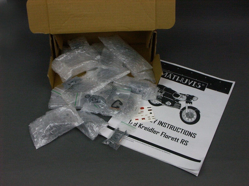
The filigree components are packed in a shatter-proof manner. A look inside the simple box
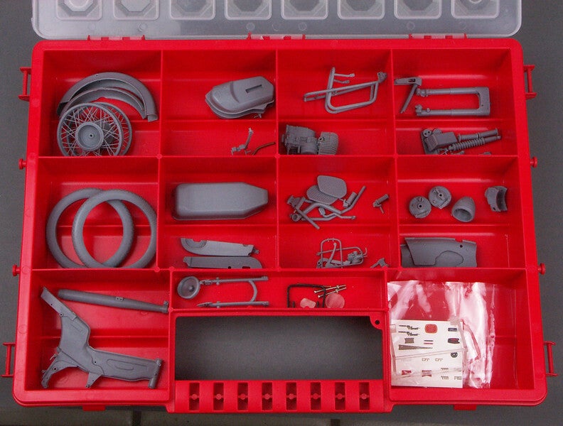
Here the components are already in the start position
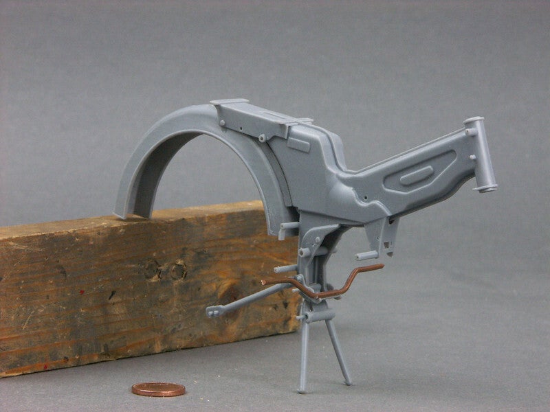
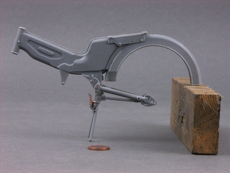
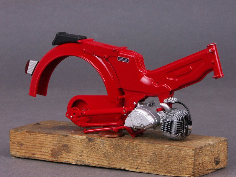
In the building instructions, each individual building section is documented with a neat graphic. I started with the frame, rear wing and the engine mount, which also has the mount for the exhaust. The footrest holder is made of a copper wire that is already glued (or imprinted?) into the frame.
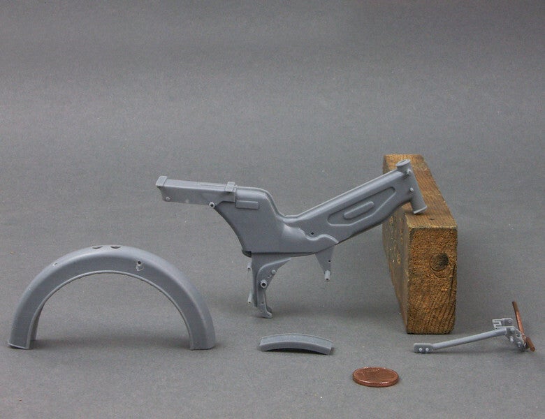
This is what the whole thing looks like. The parts are printed very cleanly and true to the original.
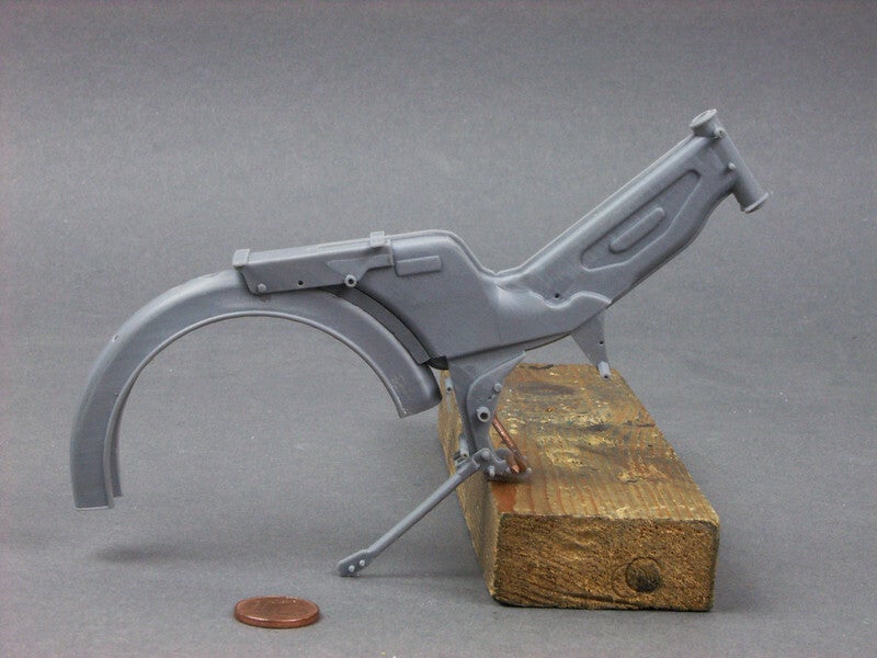
The main stand is only clamped in and is movable
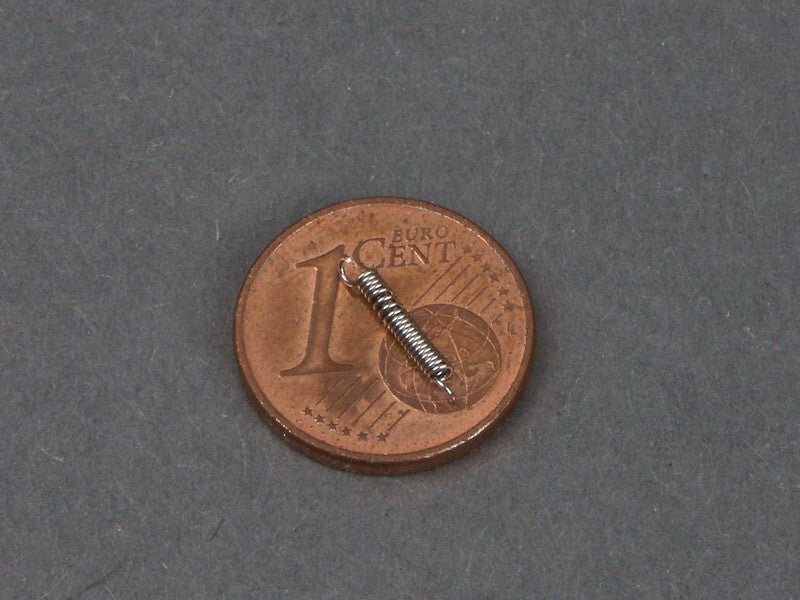
I turned a return spring from stainless steel wire
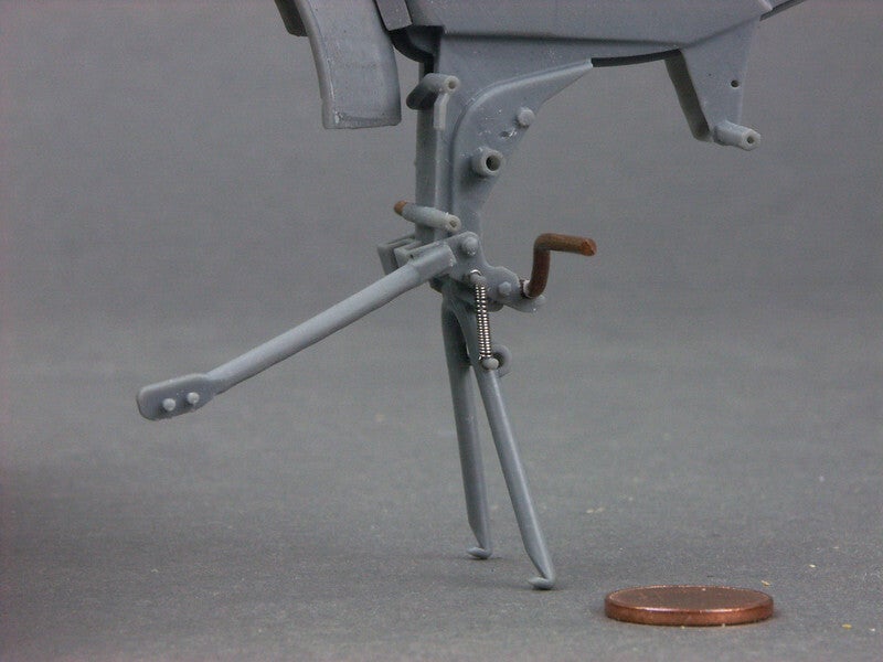
Here it finds its place
Trying on the rear swing arm, which is supported on a copper wire
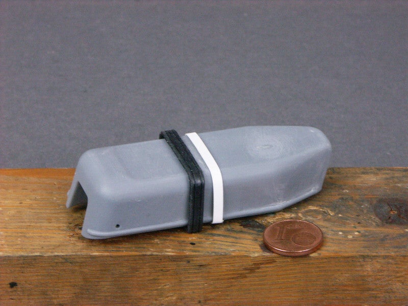
I have already done the seat and filed it a little slimmer. I also glued an Evergreen strip in place of the somewhat coarse. I glued in an Evergreen strip. This looks like this - in comparison
But it is also a fact that Jens has optimised the seat and the luggage rack, among other things. The current kits that are now being delivered look even more authentic.
The next step is the motor. For me, as a 3D printing layman, it is inconceivable how one can construct and print such a complex structure with such level of detail and print it "in one piece".
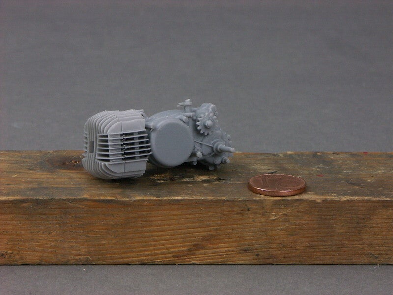
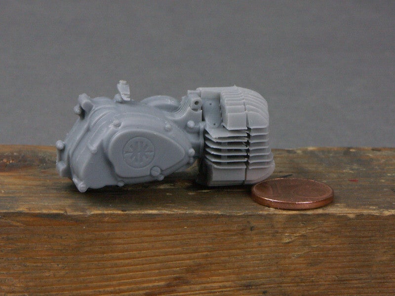
I used a plastic washer with a diamond dust coating (from dental technology) to enlarge the gap between the cylinder and the cylinder cover and straightened the cooling fins on the left/side in the area of the alternator/pole wheel cover.
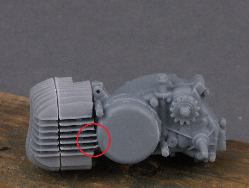
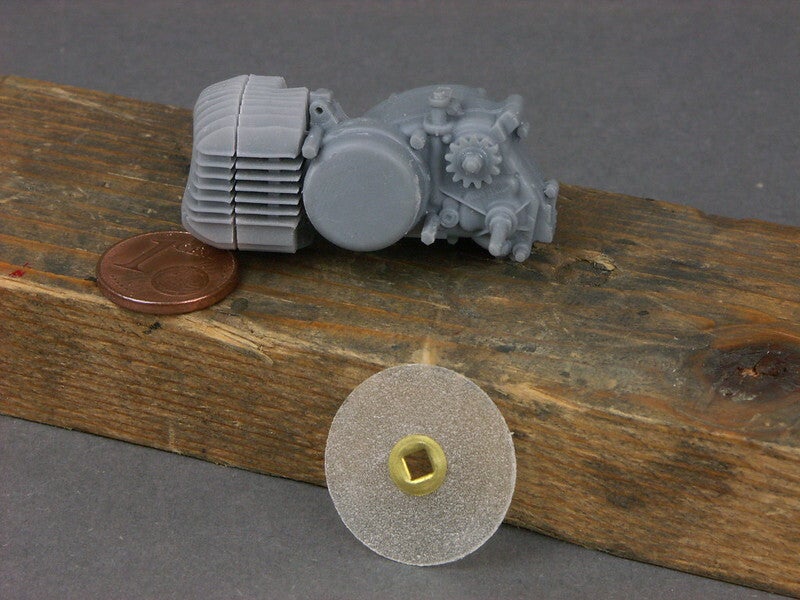
Even the struts between the cooling fins, which are supposed to keep the whirring noises at high speeds in check, are present.
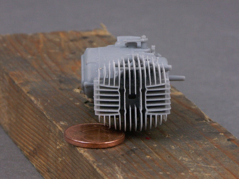
Small sample fit
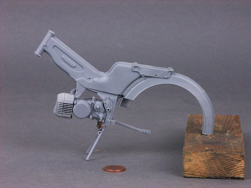
And on we go.
The carburettor looks great
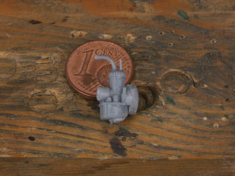
Adjustment screws and even the lettering BING are visible
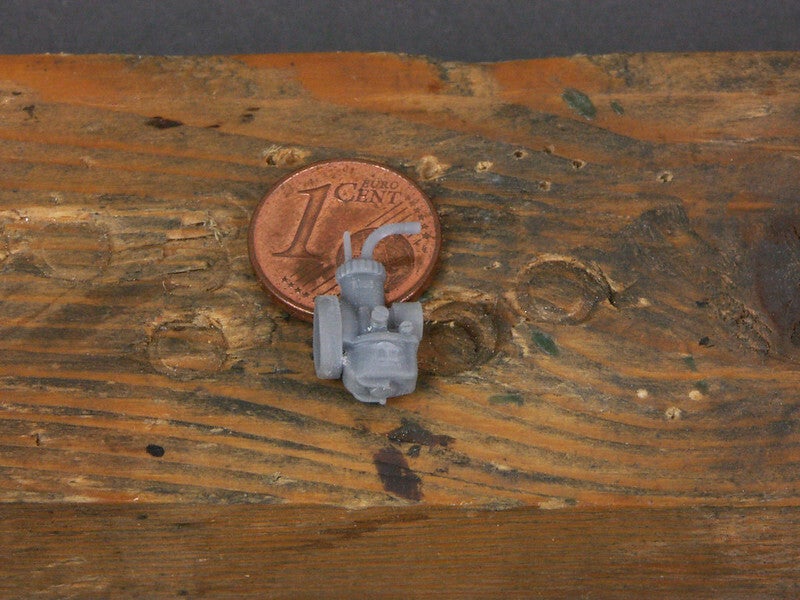
The finishing touches are done after painting.
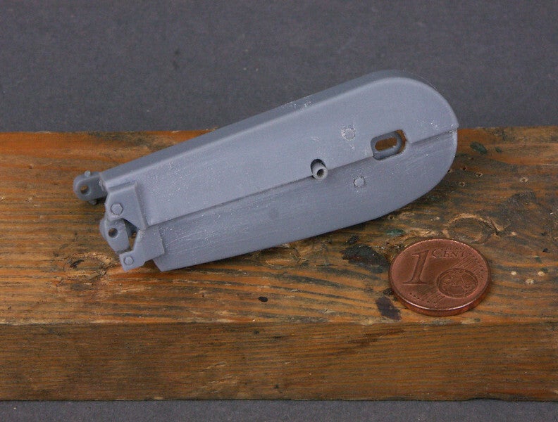
The chain guard should actually be fitted after the swingarm has been installed. I brought this step forward and I'm glad I did, because it was a bit tricky.
The next step is to prepare the wheels. For me as a 3D layman it is unimaginable how you can print a complete wheel "in one piece". But apparently it is possible
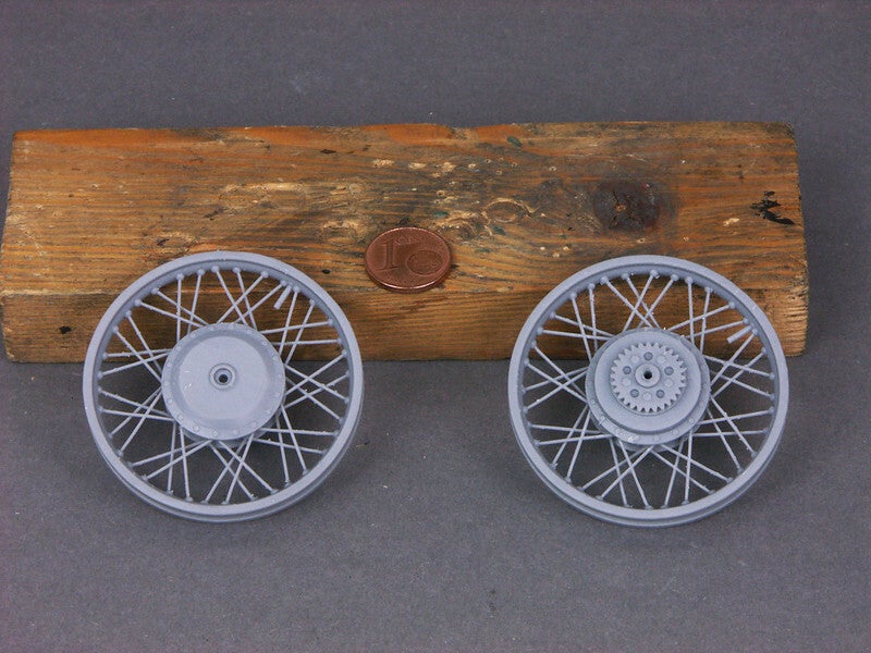
Since I want to use wire spokes, the first thing I have to do is drill holes in the rims that correspond to the course of the spokes.
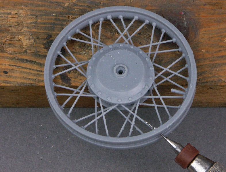
The holes in the hubs are slightly larger than the later spoke head. A little tip: The printed spokes end behind the hub shoulder. The printed spokes end behind the hub shoulder and deflect the drill if you don't remove them before drilling the holes. I have repaired the gaps in the hub shoulder with Evergreen sheet remnants.
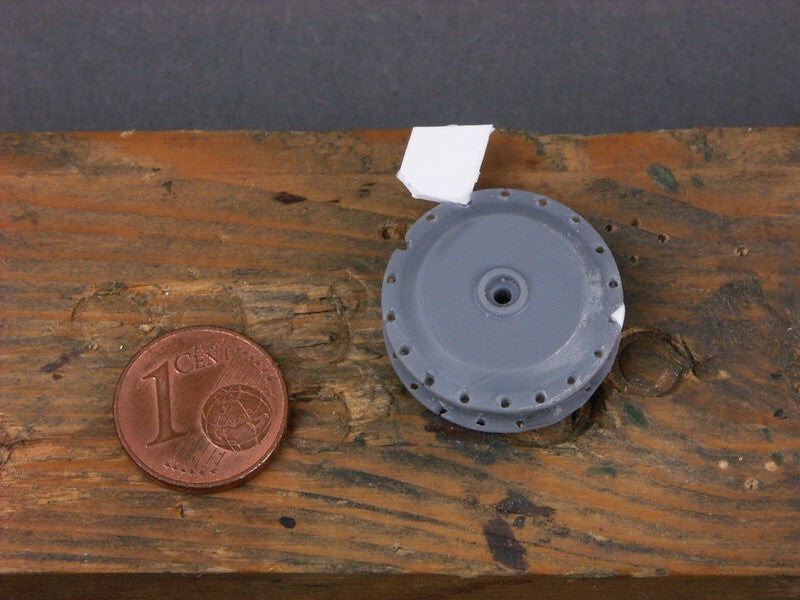
This is what the ready-to-paint parts of the front wheel look like
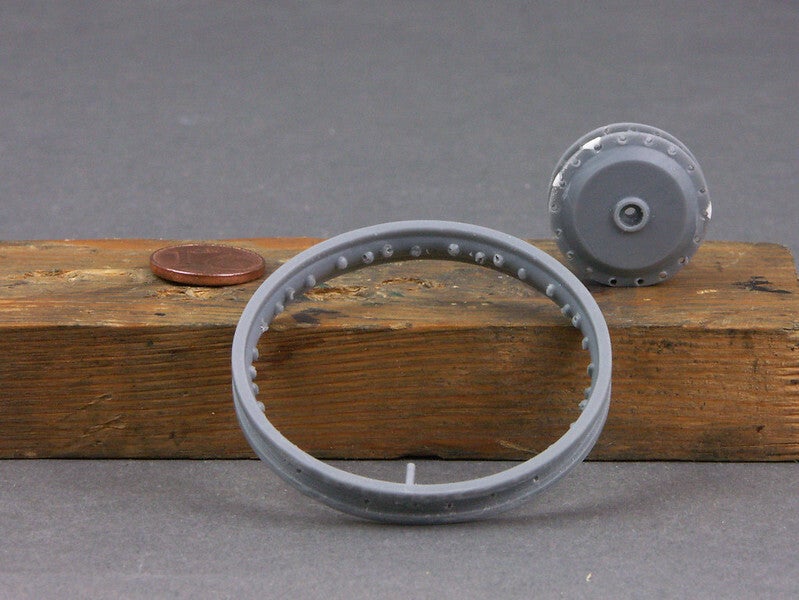
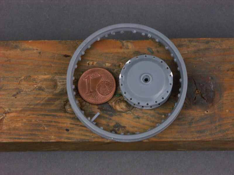
Here are the rear wheel parts
The (somewhat large) valves remain in place as orientation points for the later spoke pattern.. Later they will be replaced by more authentic metal parts.
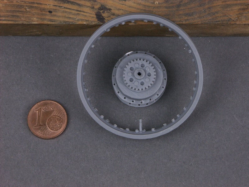
Well, I'm sure I've pimped about 100 bikes in this way. But it's still exciting every time.
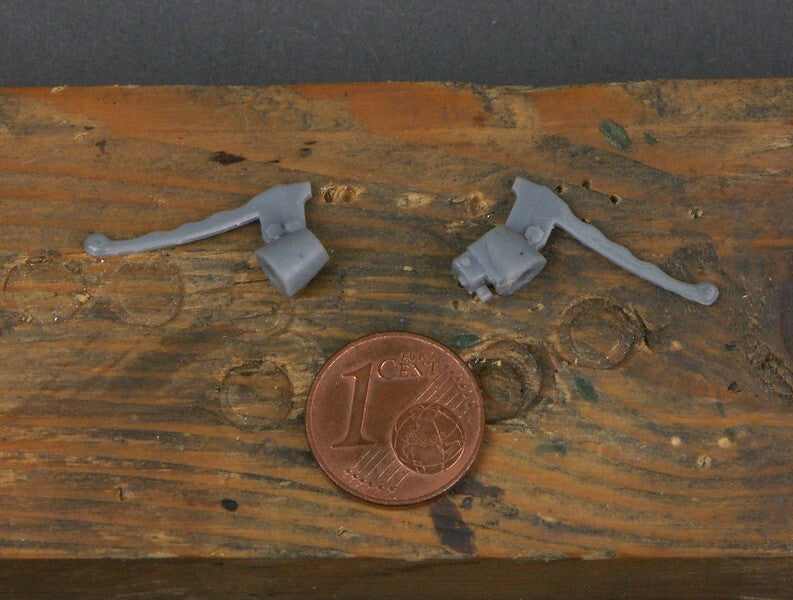
I filed the handlebar fittings a bit and optimised the spherical ends of the clutch and brake levers with a drop of decorative glue.
droplets:
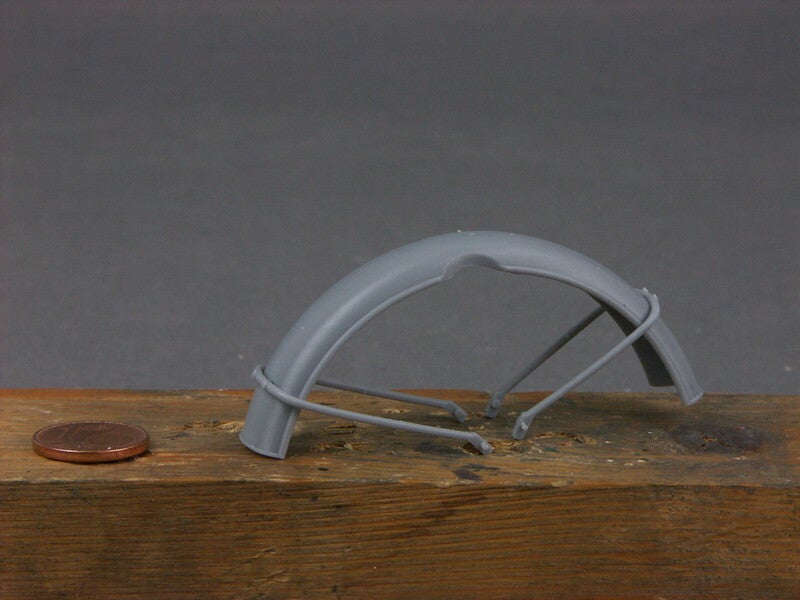
I glued the struts on the front mudguard before painting and aligned them with the fork.
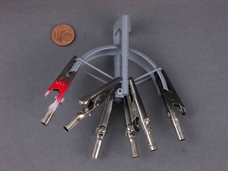
Here is the result
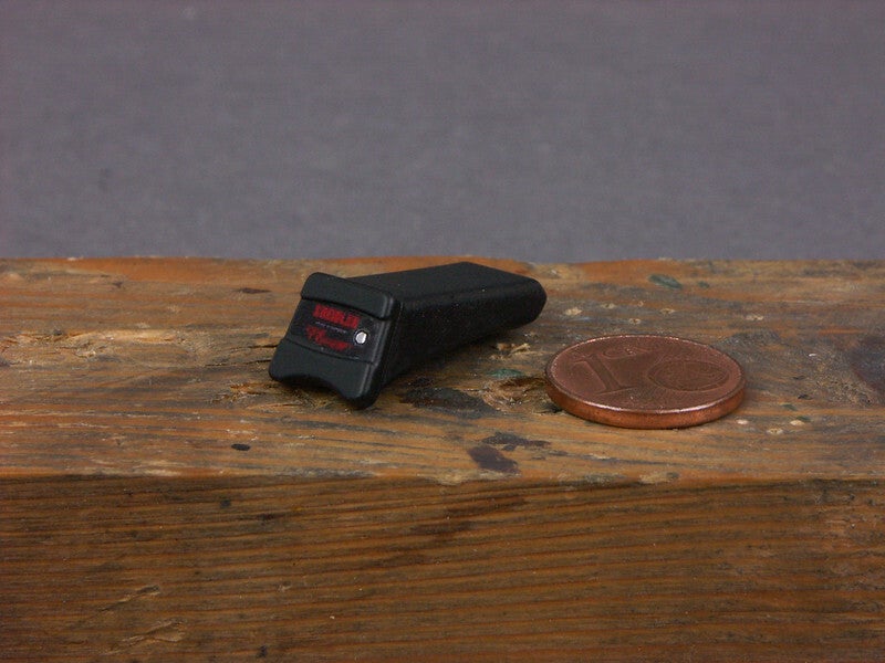
It continues colourfully - with the ready-to-install tool compartment...
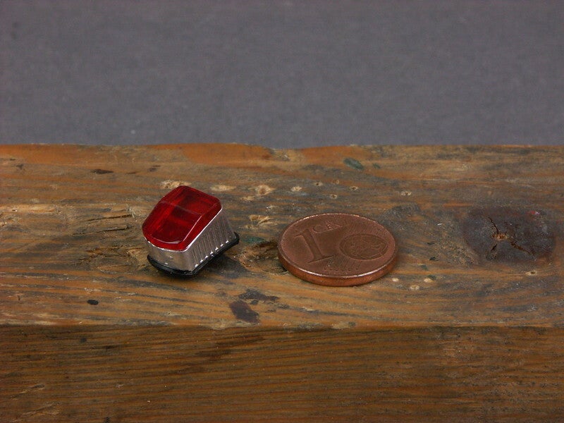
And the tail light
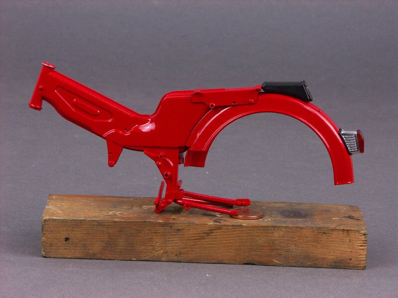
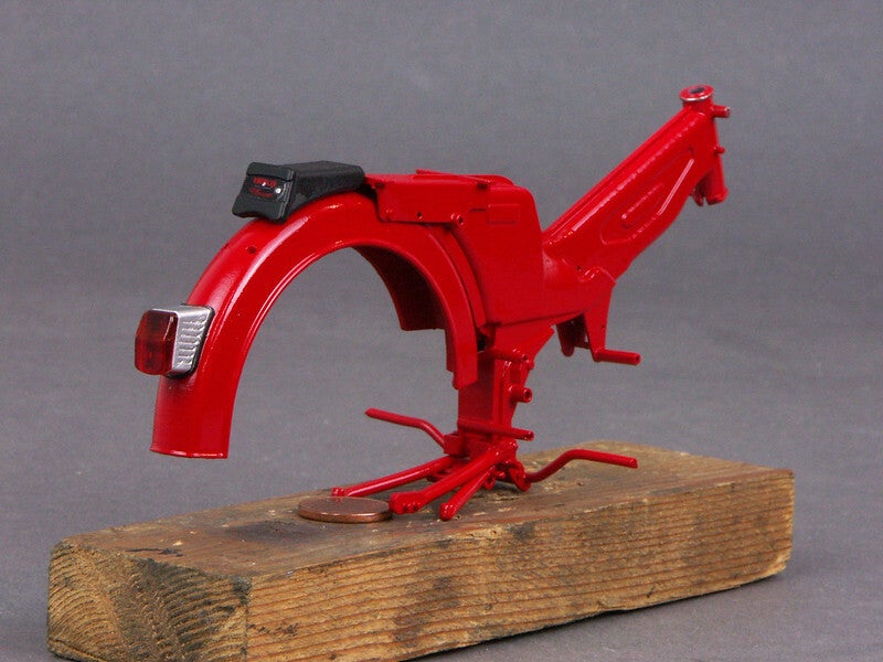
They set the first small highlights on the painted frame
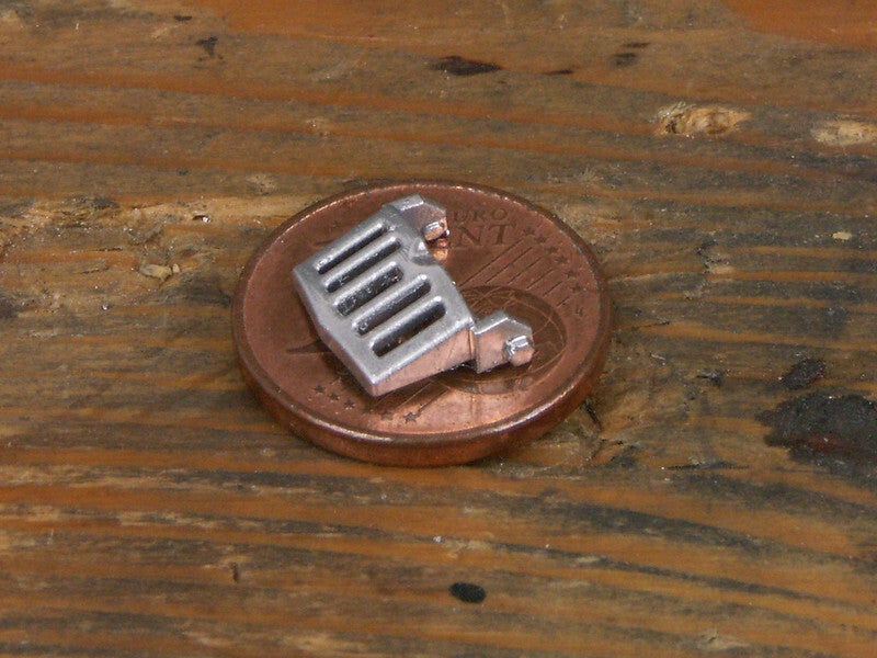
This is followed by the engine grille chrome-plated with Molotow
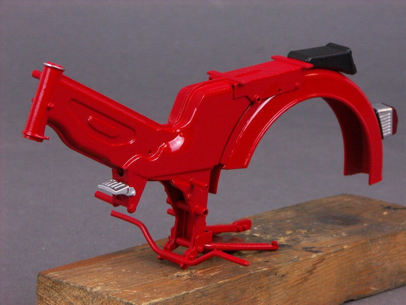
Next step - installing the rear swingarm with the chain guard
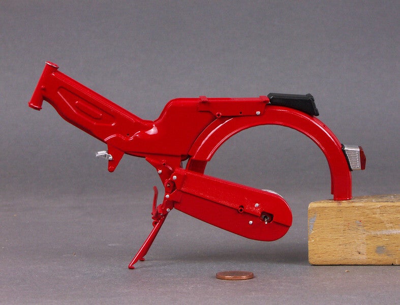
The provisionally inserted rear wheel hub acts here as a spacer
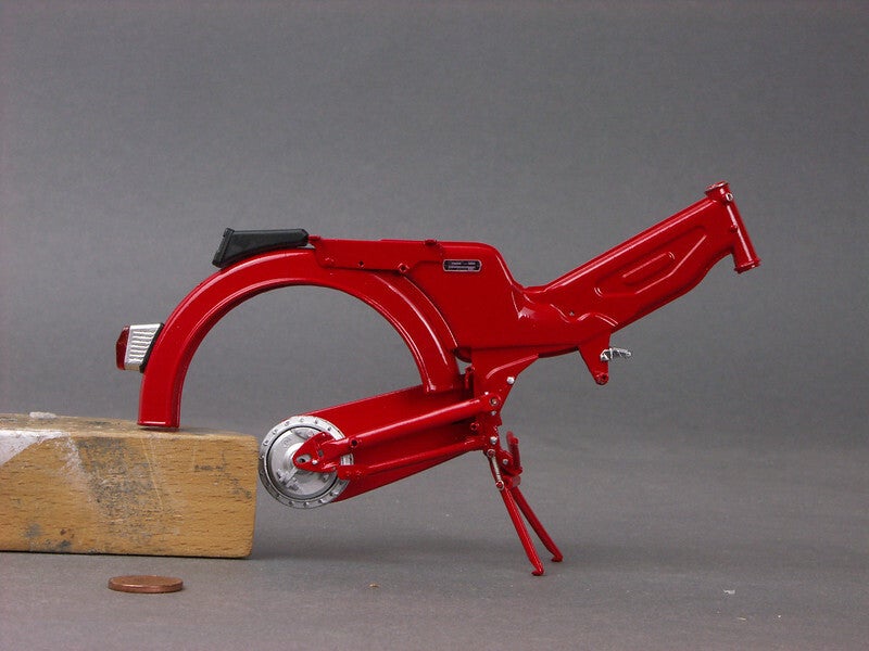
The engine has undergone a little fine-tuning after painting and installation of the spark plug
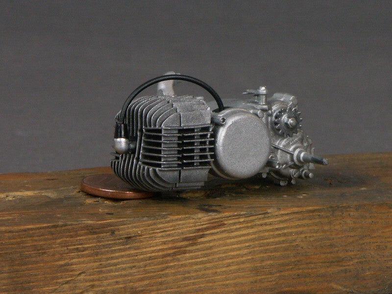
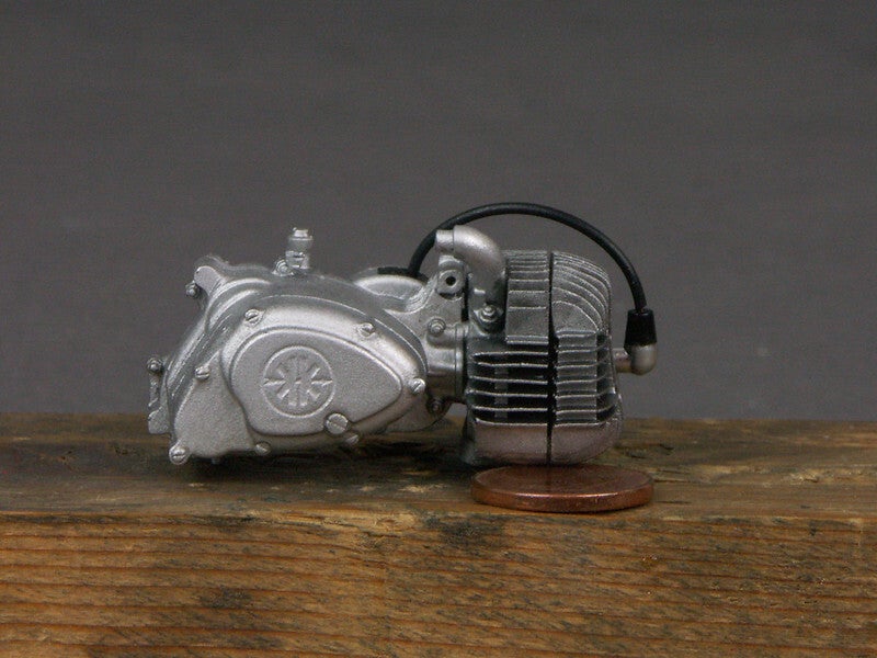
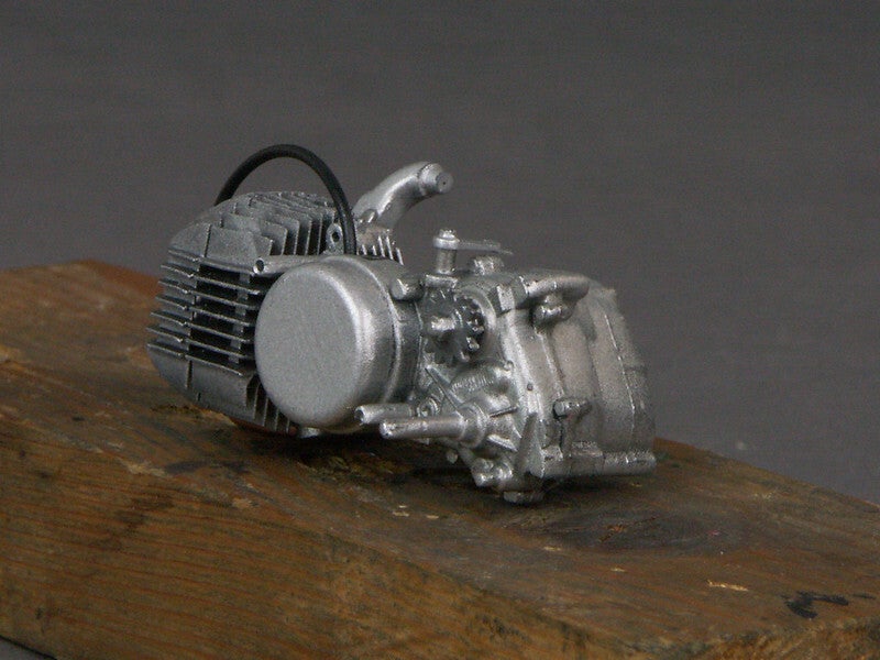
It is now ready for installation in the frame.
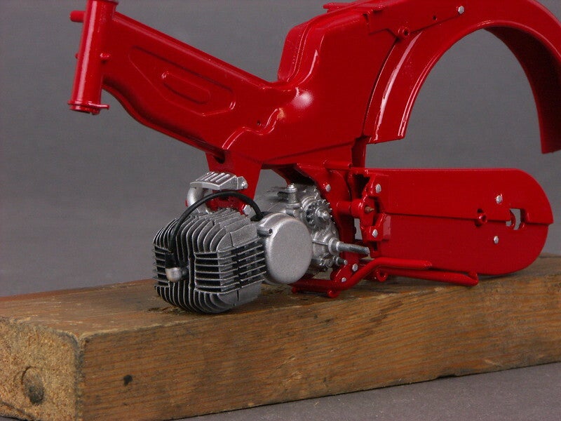
Continuing with the front fork
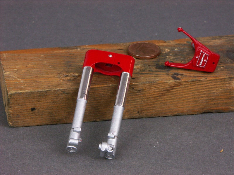
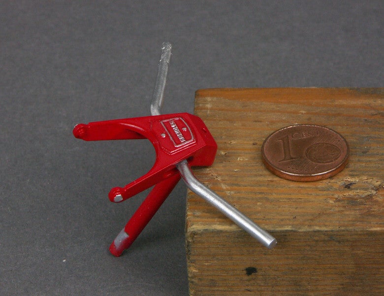
Before installation, the handlebars were glued in place.
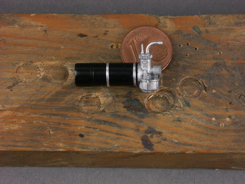
Although it is no longer visible on the finished model, I gave the carburettor an air filter made of aluminium tube. I have also I added the spring clip that holds the float chamber from a piece of wire.
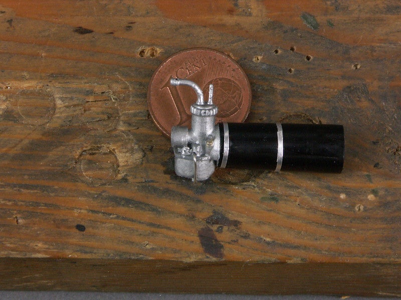
The fitting showed that there is a small gap between the carburettor flange and the intake manifold.
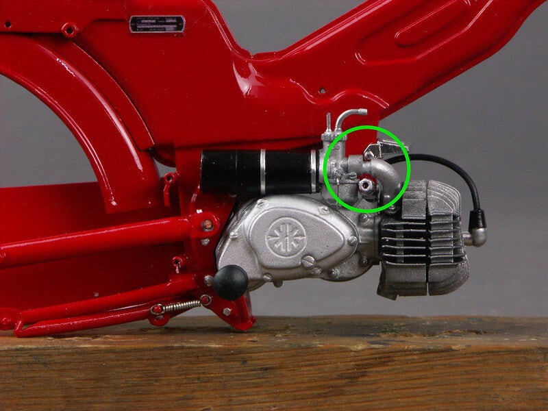
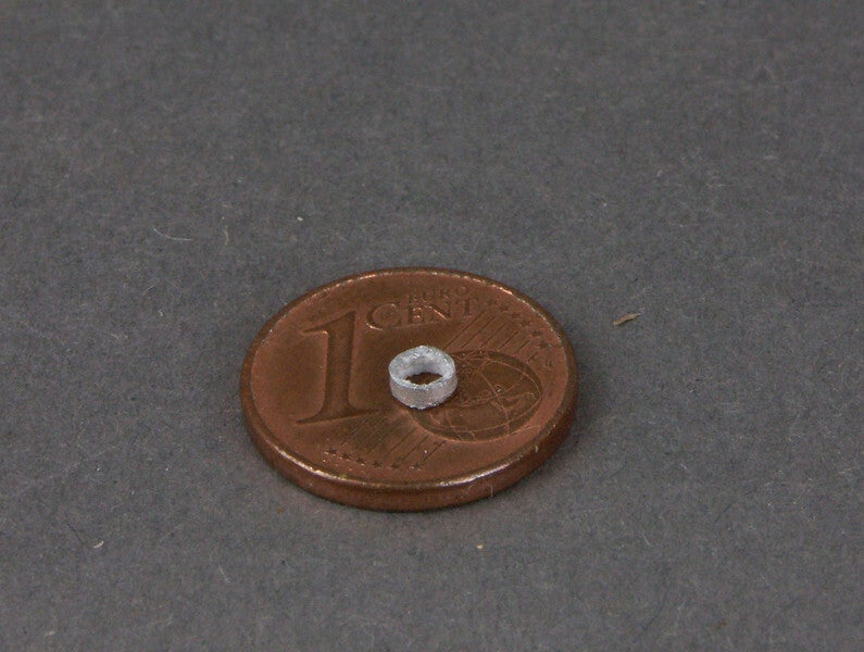
This is closed with a small piece of pipe
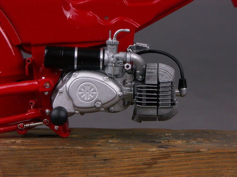
Once assembled, it looks like this
It's time for the Kreidler to stand on its own two feet. This is the starting point for the rear wheel
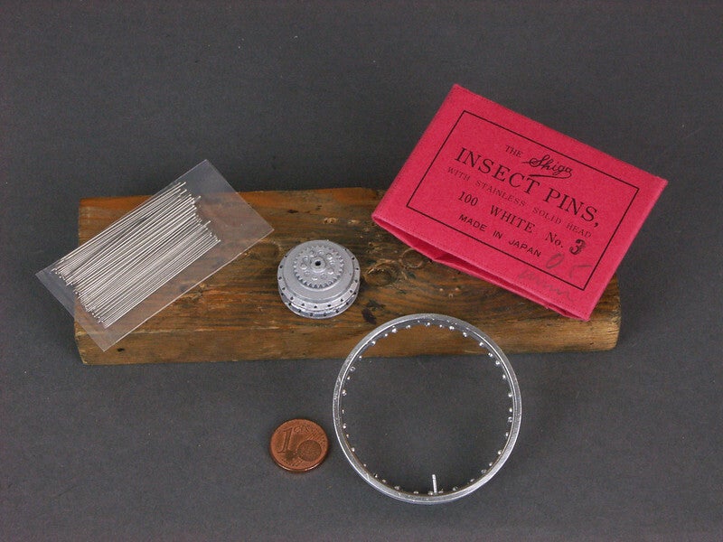
For the time being, I have left the tyre valve, which is a bit too big, in place for orientation purposes. It will be replaced later by a more authentic self-made part.
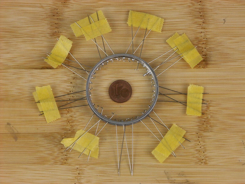
The usual patience during the lacing process was rewarded with this result
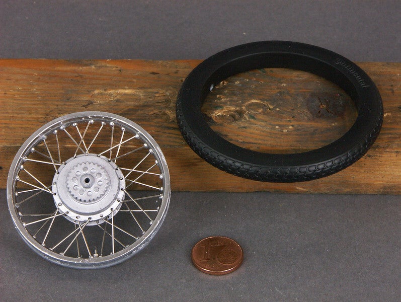
It is advantageous that the inner sides of the rims are recessed, as on the original, so that the protruding ends of the needles can be shortened without protruding. Otherwise it would not be possible to mount the solid resin tyres.
If you look closely you can see the new tyre valve, which is made of a brass screw and a piece of vinyl hose from a valve cap
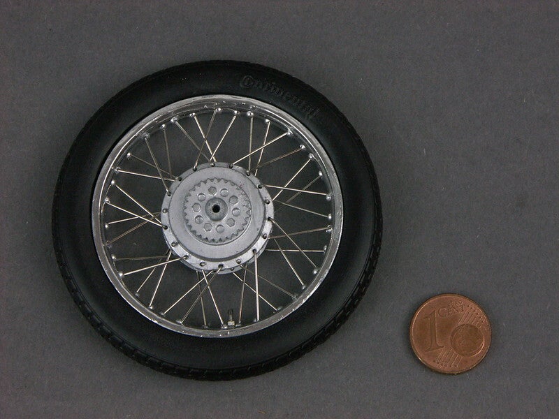
Finally, here is a group photo with front wheel
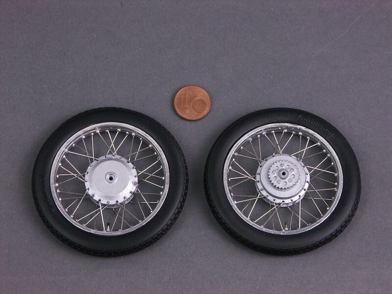
Shiga needles, however, are the best for me. Here you can see them in use
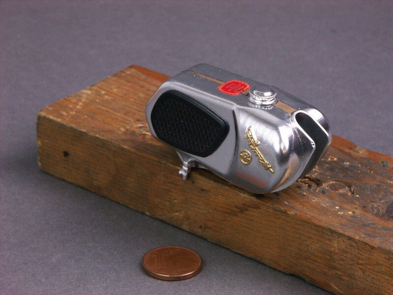
The tank was reworked with abrasives before painting. The broken petrol tap knob was replaced by a tiny piece of plastic. Now it is ready for installation
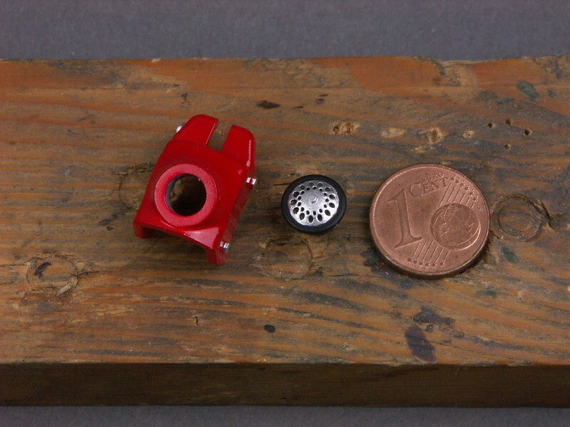
Steering head cover and horn with sealing rubber
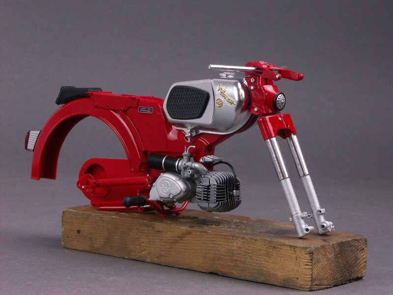
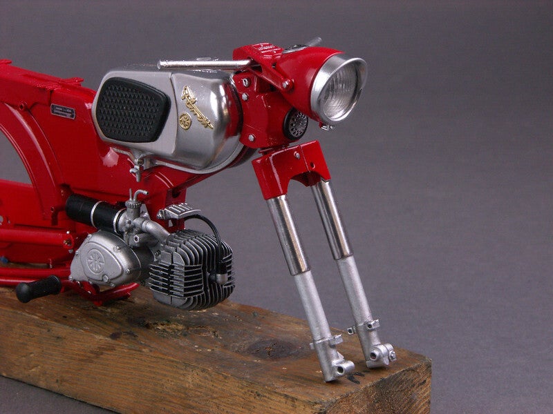
Installed - together with the fork - the whole thing now looks like this
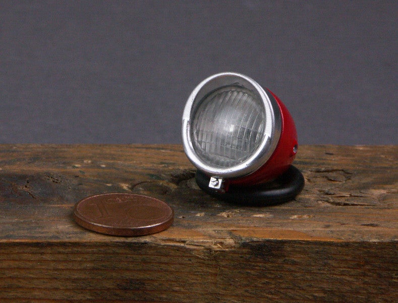
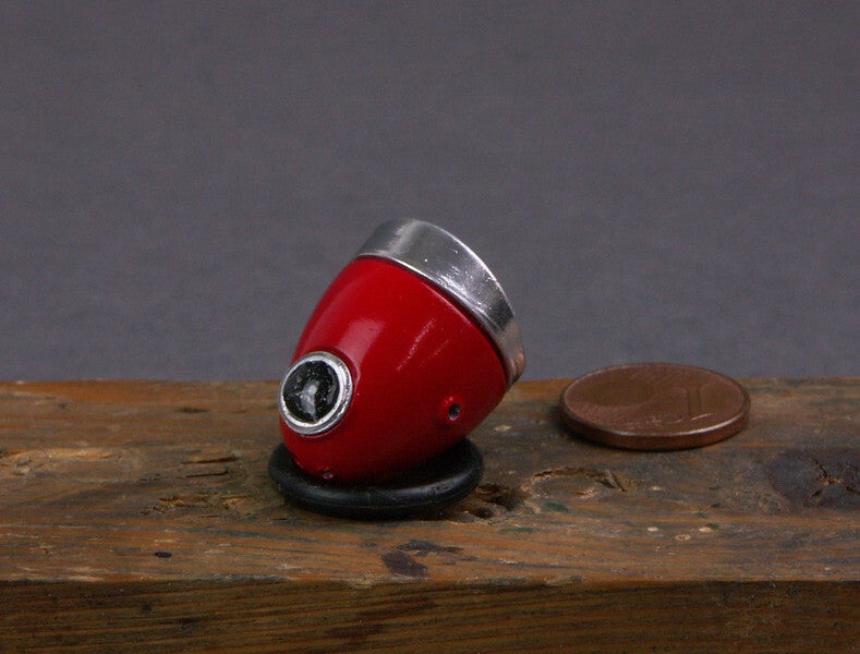
The next add-on part is the completed headlamp
The speedo glass was created from a drop of 2K glue
The machined and painted seat
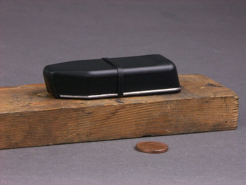
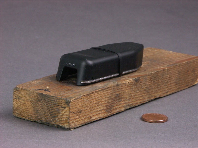
Small sample fit
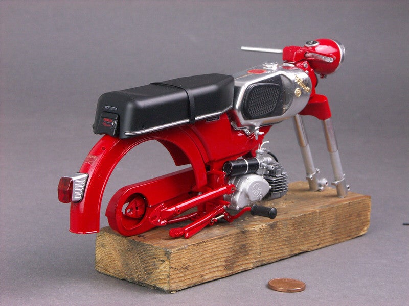
And finally the front mudguard
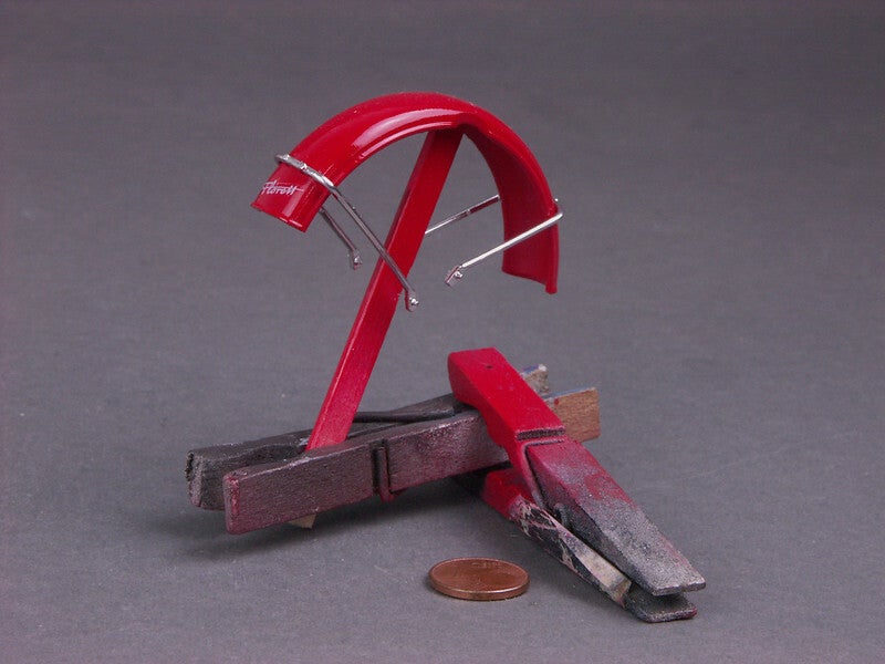
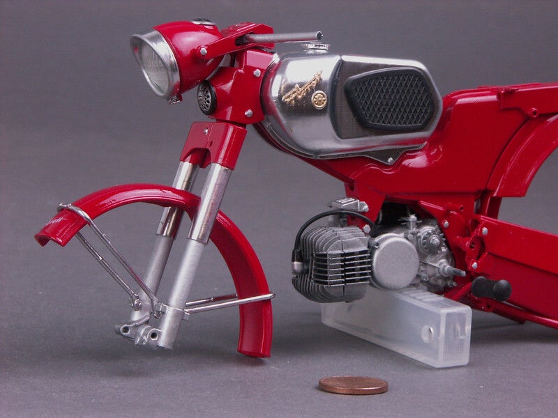
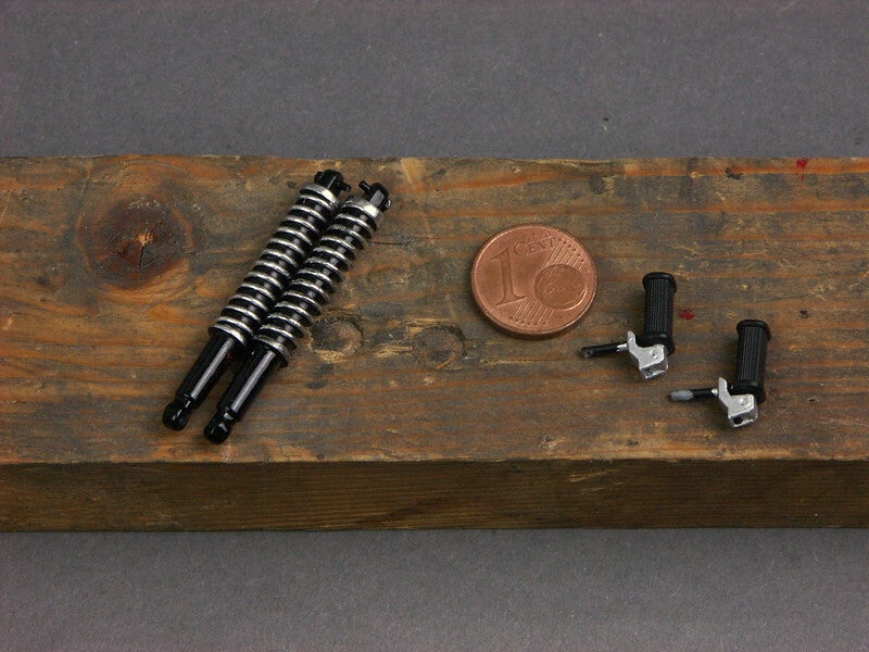
After fitting the wheels, the suspension struts can also be fitted together with the pillion footrests
And now it already looks like a real moped
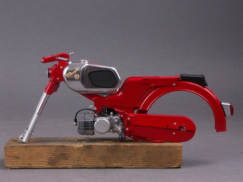
However, it also turns out that the model cannot stand on the main stand. Possible reasons: Stand a little too short, front fork a little too long. In addition, the suspension struts have obviously been designed to be "sprung in". Jacked up are "sprung out" and thus quite a bit longer. The kit also includes a transparent stand, on which the model can be on which the model can be safely placed.
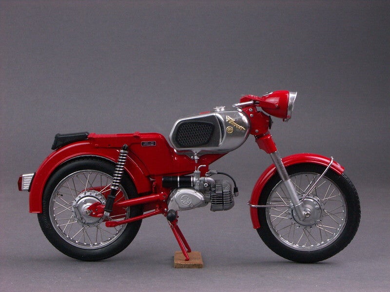
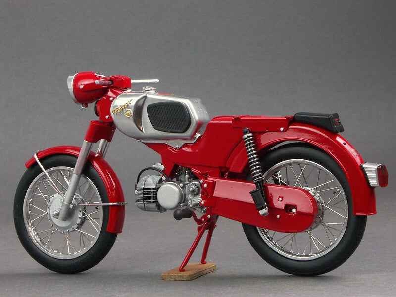
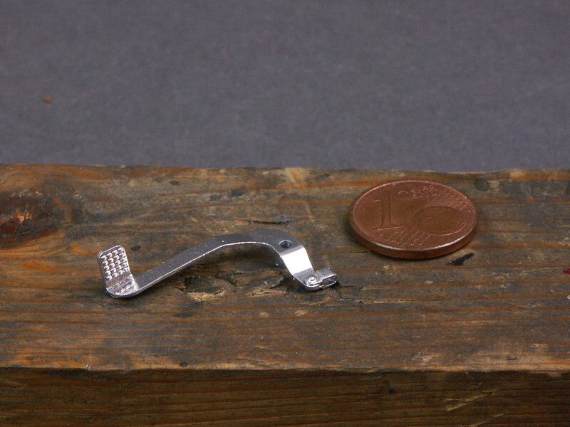
Easy to recognise - the foot brake lever
Fitted and equipped with the firing train, it then looks like this
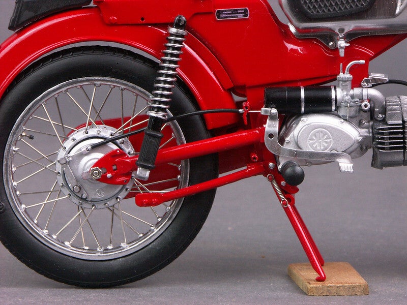
A last look at the undisguised left side - with built-in gear lever
After fitting the engine cowling, the kick starter can also be fitted
The right side after fitting the engine cowling
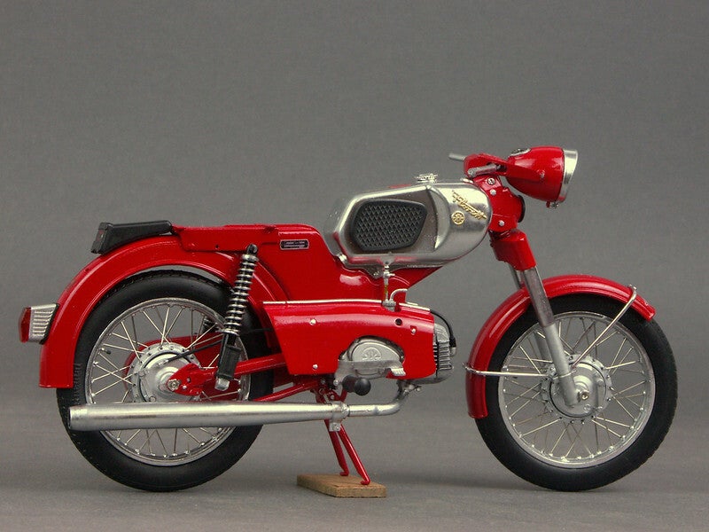
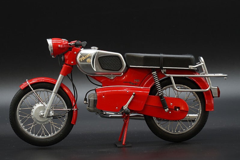
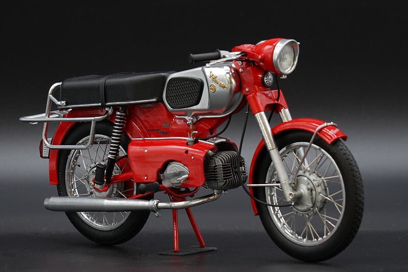
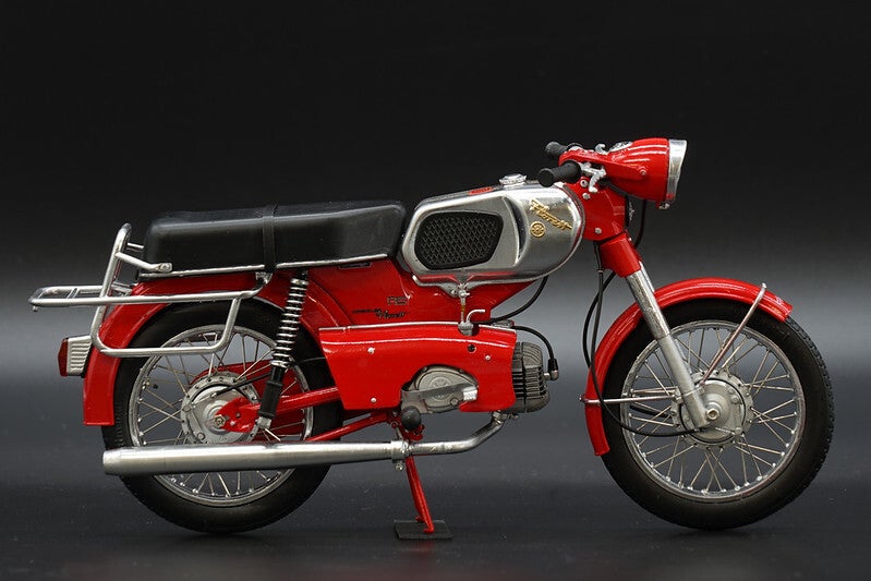
So, now the seat and luggage rack are on and the grips and handlebar fittings are in place, and the Kreidler is finished.
However, I still don't like the tank/seat bench line and wheel/main stand geometry. I will try to optimise that.
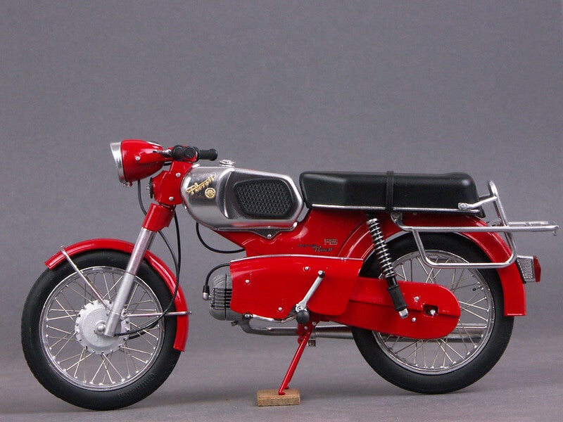
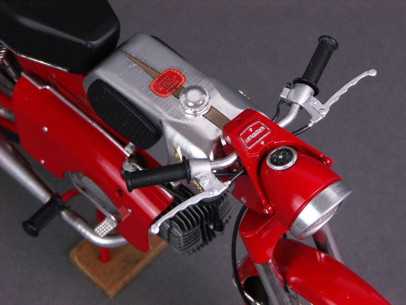
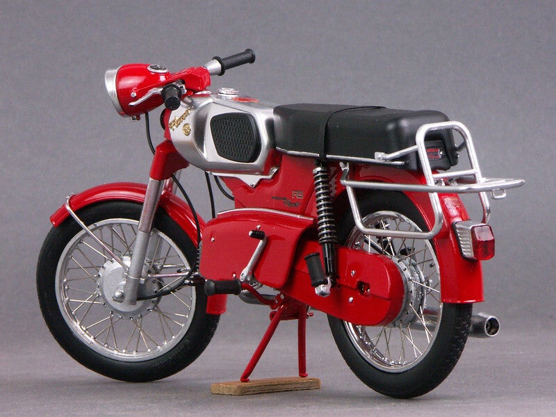
Hello everybody,
first of all many thanks for the faithful accompaniment of my construction report and the many nice comments in between and now at the end. They are still an important fuel for me in the realisation of my projects.
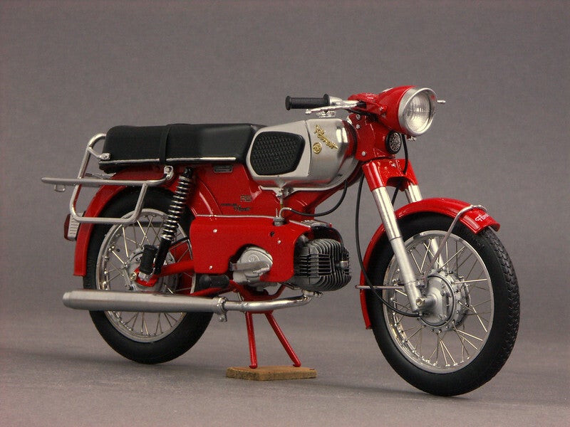
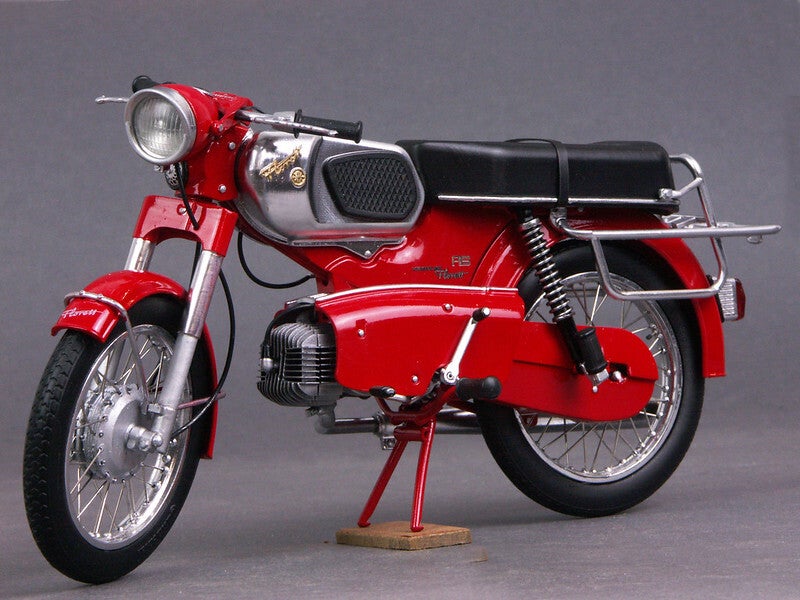
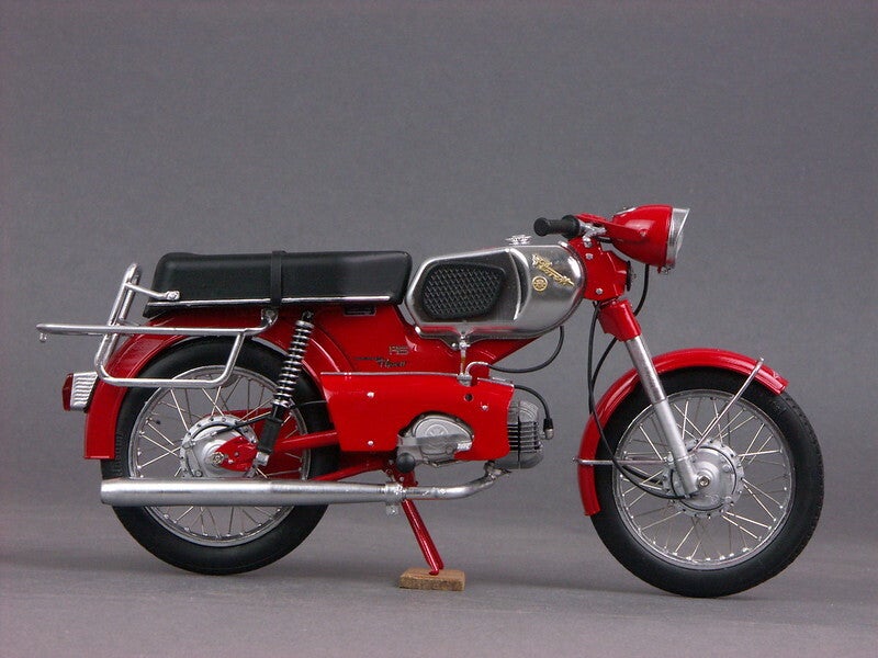
I have done the model again with the following modifications:
- Lowered the seat
- Main stand set steeper and fixed in this position.
- I shortened the lower part of the steering head.
I also added the Bowden cable grommet for the brake cable, which is also present on the original.
Greetings Peter
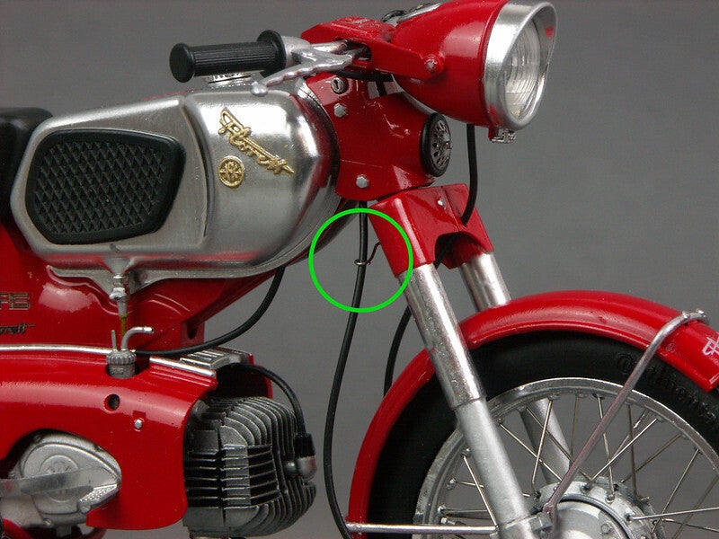
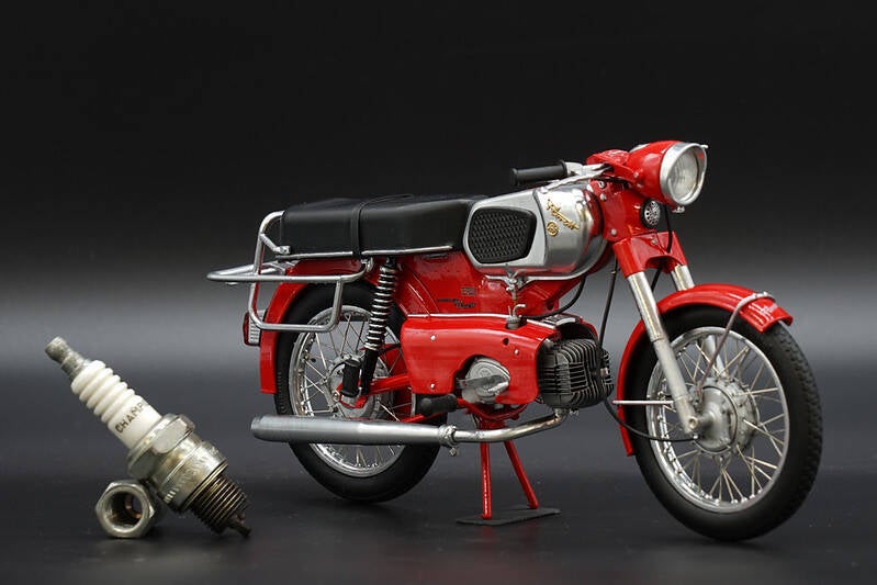
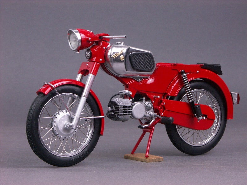
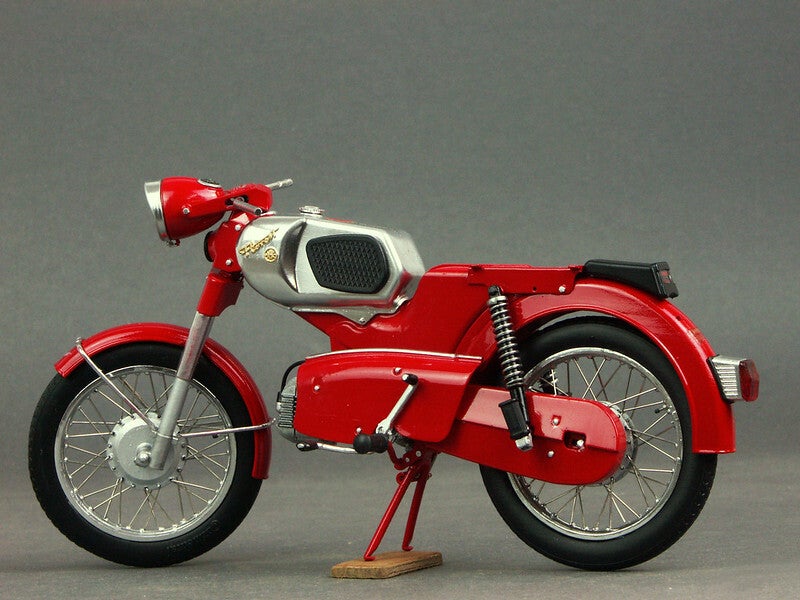
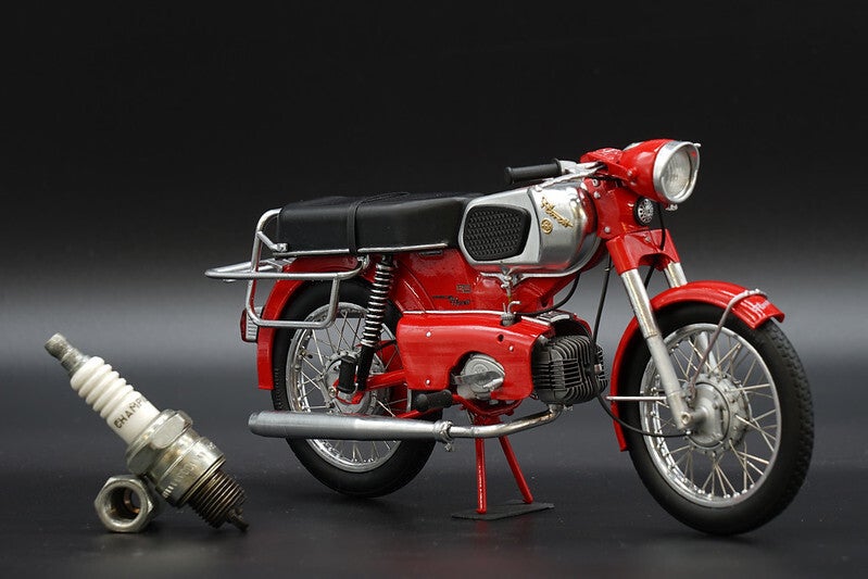
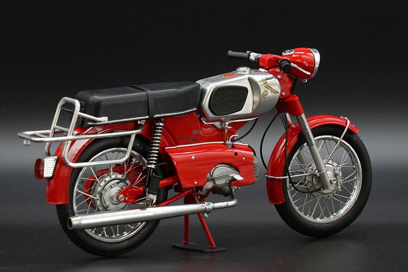
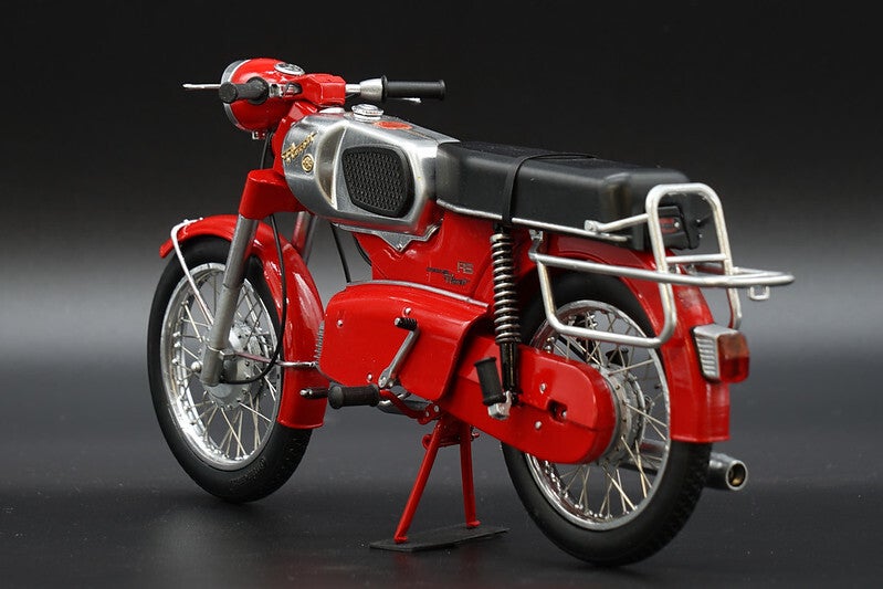
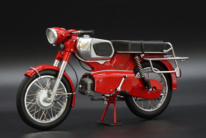
Finally, I photographed the now finished model in the photobox in full format
Create Your Own Website With JouwWeb